tds-3试水笔怎么用?
一、tds-3试水笔怎么用?
1. 将TDS-3试水笔的电极部分浸入要测试的水中,确保它被完全淹没在水中。
2. 轻轻搅动水,以确保水中的溶解固体充分混合。
3. 稍等几秒钟,直到数字显示屏跳动并停留下来,这就是水中的总溶解固体含量,以PPM(每百万份)的形式显示。
4. 使用结束后,将电极部分用纯水清洗干净,并将试水笔放回透明的保护套中,以避免受到污染或损坏。
需要注意的是,使用TDS-3试水笔时,应该选择适当的读数范围,并尽可能避免将它暴露在高温或极端潮湿的环境中。同时,这个仪器也需要进行定期的校准,以确保它的准确性和可靠性。
二、tds-3水质检测参考值?
小于等于1000毫克每升。tds值越高,表示水中含有的杂质越多,杂质通常指水中钙离子、镁离子、钠离子、钾离子等离子的浓度,并无法直接表示水质好坏。
所以,tds过高(超过600以上)确实表明水质不好,但tds越低,并不等于水质就越好。
三、tds-3水质检测笔功能?
TDS-3水质检测笔是一种便携式水质检测仪器,用于测量水体中的总溶解固体(Total Dissolved Solids,TDS)含量。它具有以下主要功能:
1. TDS测量:TDS-3水质检测笔可以测量水中的溶解性离子、矿物质、溶解化合物等总量。这些物质包括盐类、金属离子、化学物质等,其浓度对水质的好坏和适用性有着重要影响。
2. 数字显示:检测笔上通常配备有数字显示屏,可以直观地显示水中的TDS含量。这样用户可以快速了解水质的总体情况。
3. 自动温度补偿:TDS-3水质检测笔通常具备自动温度补偿功能,可以根据水温的变化对测量结果进行修正,确保测量的准确性。
4. 简单操作:水质检测笔一般采用一键式操作,用户只需将笔头浸入待测试的水中,几秒钟后即可得到测量结果。使用起来非常方便快捷。
5. 电池供电:TDS-3水质检测笔通常使用电池供电,因此它是一款可充电的设备,方便携带和使用。
使用TDS-3水质检测笔可以帮助用户了解所测试水体的整体水质情况,从而确定水质的适用性,例如饮用水、水处理、游泳池维护等方面。但请注意,TDS测量只能提供水中溶解物的总量,对于具体溶解物的种类和含量还需要进一步的化学分析。
四、tds-3水质检测参考表?
水质tds的标准正常都是小于等于1000毫壳/升,所谓水质tds的标准就是检测水源当中的杂质是否合格,水当中的杂质越多代表tds值就会越高,一般不符合tds值标准的水人体是不可以饮用的。
五、tds-3怎么区分水质好坏?
TDS和水质好坏是两个不同的概念。TDS只是众多水质指标中的一个指标,tds主要是用来检测纯净水、蒸馏水、RO膜(反渗透膜)净水器出水水质的指标之一。
TDS是总溶解性固体物质TotalDissolvedSolids的英文首字母缩写,是指水中总溶解性物质的浓度,单位毫克/升(mg/L),主要反映的是水中Ca2+、Mg2+、Na+、K+等离子的浓度,与水的硬度、电导率有较好的对应关系,TDS越小,水中Ca2+、Mg2+、Na+、K+等离子的浓度越低,电导率越小。
但TDS小,并不就表示水质好,TDS大,也不表示水质差。合格的饮用水必须满足微生物指标(细菌数)、毒理指标(重金属离子浓度)、感官性状(色、嗅、味、肉眼可见物)和一般化学指标以及放射性指标。健康洁净的生活饮用水必须不得含有病原微生物,水中化学物质、放射性物质不得危害人体健康,感官性状良好。
六、tds-3水质检测仪可靠吗?
不靠谱。使用水质检测笔只能能够大概的评判一下水质的理化标准,并不能通过这个数据直接的判断水质的好坏,而水质检测笔主要就是可以检测水的TDS值,也可以检测出水的导电率,但是单凭一个TDS值是没有办法判断出水质的真实情况的
七、tds-3试水笔正常值多少?
tds-3试水笔正常值200-300之间,
时比较正常。通常情况下,测量水质主要看的是硬度和ph,只要这两个数值控制住,tds的值就会正常。根据鱼儿的习性,要将水质调节为弱酸性或弱碱性,硬度一般不能太高,软水更适合养鱼。另外还要控制好水温,尤其是养热带鱼,温度保持在20-30℃之间。
一般情况下,电导率越高,盐份越高,TDS越高。在无机物中,除溶解成离子状的成分外,还可能有呈分子状的无机物。由于天然水中所含的有机物以及呈分子状的无机物一般可以不考虑,所以一般也把含盐量称为总溶解固体。 但是在特定水中TDS并不能有效反映水质的情况。
八、电路图?
画电路图需要先找好图形绘制工具 与工具相结合 能更快 更好的提高工作效率 不耽误时间 现在市场上的亿图图示功能很强大 操作简单
九、tds-3水质检测仪检定规程?
Tds—3水质检测仪检定规程
Tds值越高就表示,水中含有的杂质越多,这其中的杂质通常指的是水中钙离子,镁离子,钠离子,钾离子等离子的浓度并无法直接表示水质的好坏,所以tds过高确实表明水质不好,但tds越低并不等于水质就越好。
中国制定的饮用水标准
自来水300 ppm以下
纯净水50 ppm以下
矿泉水100至200 ppm之间
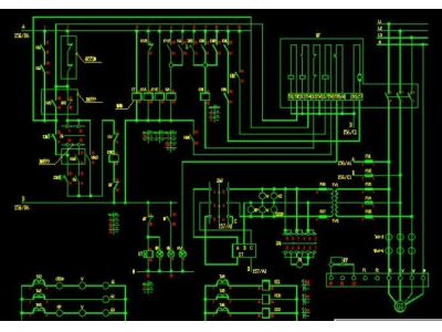
十、探照灯电路图
探照灯电路图: 理解、构建和优化探照灯
探照灯是一种广泛应用于舞台演出、户外照明和应急照明等领域的强光照明设备。在探照灯的核心部件之一是它的电路板,负责控制和供电。本文将带您深入了解探照灯电路图的构建和优化,帮助您了解探照灯的工作原理,并提供指导以构建高效可靠的探照灯。
了解探照灯电路图
探照灯电路图通常包括多个关键组件,如电源模块、控制模块、光源模块等。通过仔细研究电路图,您可以了解到这些组件之间的连接方式和信号传输原理。
在电路图中,常见的连接方式包括并联和串联。并联的组件同时接收相同的电压,但电流被分流到各个组件;串联的组件则依次接收电压,电流在各个元件之间相等。
此外,探照灯电路图中的控制模块通常包括变阻器、电位器和开关等元件,用于调节和控制亮度、色温等参数。
构建探照灯电路图
构建探照灯电路图需要具备一定的电子电路基础知识。以下是构建探照灯电路图的基本步骤:
- 确定探照灯的功率需求和光照要求。
- 选择合适的电源模块,确保其输出电压和电流满足探照灯的需求。
- 设计控制模块,包括亮度调节、开关控制和保护电路。
- 选择合适的光源模块,如LED光源。
- 根据电路图进行元件的连接和布局。
- 进行电路测试和参数调整,确保探照灯的性能符合要求。
优化探照灯电路图
优化探照灯电路图可以提高探照灯的性能和稳定性,延长其使用寿命。以下是一些优化措施:
- 选择高效能源: 选择高效的电源模块,以减少能量损耗和发热。
- 合理布局: 在电路板上合理布局组件,减少信号干扰和高温区域。
- 保护电路设计: 添加过流保护、过压保护和短路保护等保护电路,提高探照灯的安全性。
- 使用优质材料: 选择优质元件和材料,降低故障率和损耗。
- 热管理: 针对高功率探照灯,设计风扇散热模块,保持其正常工作温度。
结论
探照灯电路图是构建和优化探照灯的重要参考。通过深入了解电路图,您可以更好地理解探照灯的工作原理,并根据需求构建高效可靠的探照灯。优化探照灯电路图可以提高探照灯的性能和稳定性,延长其使用寿命。希望本文对您进一步了解和构建探照灯有所帮助。
Translated text in English: htmlFlashlight Circuit Diagram: Understanding, Building, and Optimizing Flashlights
A flashlight is a powerful lighting device widely used in stage performances, outdoor lighting, and emergency illumination. One of the key components of a flashlight is its circuit board, which is responsible for control and power supply. This article will take you through the understanding, building, and optimization of flashlight circuit diagrams, helping you grasp the working principles and provide guidance for constructing efficient and reliable flashlights.
Understanding Flashlight Circuit Diagrams
A flashlight circuit diagram typically consists of several essential components such as power modules, control modules, and light source modules. By studying the circuit diagram closely, you can understand how these components are connected and the principles of signal transmission.
In circuit diagrams, common connection methods include parallel and series connections. In parallel, the components receive the same voltage simultaneously, but the current is divided between them. In series, the components receive the voltage sequentially, and the current is equal between the elements.
In addition, the control module in the flashlight circuit diagram often includes components such as variable resistors, potentiometers, and switches to regulate and control brightness, color temperature, and other parameters.
Building Flashlight Circuit Diagrams
Building a flashlight circuit diagram requires a certain level of knowledge in electronic circuits. The following are the basic steps for constructing a flashlight circuit diagram:
- Determine the power requirements and lighting needs of the flashlight.
- Select a suitable power module to ensure its output voltage and current meet the requirements of the flashlight.
- Design the control module, including brightness adjustment, switch control, and protection circuits.
- Select a suitable light source module, such as LED light sources.
- Connect and layout the components according to the circuit diagram.
- Conduct circuit testing and parameter adjustment to ensure the flashlight's performance meets the requirements.
Optimizing Flashlight Circuit Diagrams
Optimizing flashlight circuit diagrams can improve the performance, stability, and longevity of flashlights. Here are some optimization measures:
- Choose efficient power sources: Select high-efficiency power modules to reduce energy loss and heat generation.
- Proper layout: Arrange components on the circuit board in a manner that reduces signal interference and high-temperature areas.
- Protection circuit design: Add protection circuits such as overcurrent protection, overvoltage protection, and short circuit protection to enhance flashlight safety.
- Use high-quality materials: Choose quality components and materials to lower failure rates and losses.
- Thermal management: Design fan cooling modules for high-power flashlights to maintain normal operating temperatures.
Conclusion
A flashlight circuit diagram is a crucial reference for building and optimizing flashlights. By gaining a deeper understanding of the circuit diagram, you can better comprehend the working principles of flashlights and construct efficient and reliable flashlights according to the requirements. Optimizing flashlight circuit diagrams can enhance performance, stability, and lifespan. We hope this article helps you further comprehend and build flashlights.